Transient Forces
- Computations
In accordance with Newton's Third Law, the force exerted on the piping by the conveyed liquid is equal and opposite to that applied on the liquid by the piping. On physical grounds, the latter is due to the following causes: gravity, fluid friction drag, and changes in pipe diameter and/or direction.
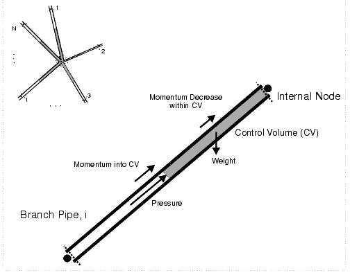
The linear-momentum and action-reaction principles are applied to an appropriate control volume (CV) to construct general formulae for instantaneous forces applied to pipe walls by the conveyed liquids. Specifically, a fixed control volume is defined as being centered around a node, which can be internal (associated with multiple pipes) or external (at the end of exactly one pipe) as illustrated in Figure 14-14: Control Volume for Internal Node or Figure 14-15: Control Volume for External Node , respectively.
Figure 14-14: Control Volume for Internal Node
Figure 14-15: Control Volume for External Node
It is assumed that HAMMER has already computed the transient flow/velocity and head/pressure for every end point and at each relevant instant. Then, the following relation must hold:
Net force on the liquid in CV = rate of increase of momentum within CV + momentum flowrate out of CV boundary surface (CS)
Therefore, after collapsing the CV onto the junction or node:
ρ g ΣiAi (Hi - Z) ni + R = ρ Σi (- Qivi)
where the subscript i refers to the i th pipe emanating from the node, r is mass density, g is acceleration due to gravity, H is head, Z is elevation, n is the unit inner normal to the CS, A is cross-sectional area, R is the resultant force exerted by the pipe on the liquid, t is time, v is the fluid velocity, and Q is the flowrate towards the node. Note that any boldfaced underlined quantity is a vector.
By rearranging (), it follows that the reaction force on the pipe, applied by the liquid, is given by the vector formula:
P = -R = ρ ΣiAi [vi2 + g (Hi - Z) ] ni
where σi = +1, if the flow in the branch is directed towards the node, and -1 otherwise. On account of the discretization involved, this force is apportioned equally to each of the end points situated at the node.
The first term on the right-hand side of (), which involves v, is associated with momentum flowing across the boundary CS. All terms are functions of time, except for the transverse component of weight which acts in the downward direction -k, where k is a unit vertical upward vector. The longitudinal (or axial) component of weight (if any), a body force on the CV, is already accounted for in the hydraulic transient equations used by Bentley HAMMER CONNECT to solve for flow/velocity and head/pressure at each instant.
In terms of the Cartesian coordinates, with z being measured vertically upward, the magnitude of the resultant force P = (Px , Py , Pz ) = -R = (-R x , -R y , -R z ) on the pipe is given by:
P = R = | -R | = [Rx2 + Ry2 + R z2] 0.5
For instance, in the case of an internal node as in Figure C-1 with N = 2, vertical pipes meeting at an angle of 180 degrees, and steady flow, then the magnitude of the resultant is given by the relation ρg | H 2 A 2 - H 1 A 1 |. For steady flow in a vertical pipe discharging to atmosphere through an orifice at its top end as in Figure C-2, the resultant downward force on the pipe is ρQ|V - v|, with Q, V, and v being the flow and velocity at the vena contracta and in the pipe, respectively.
The result of the force computations may be restricted to periodic times, as indicated in Transient Solver Calculation Options > Report Times. If the forces are enabled in the Run Dialog, a table of maximum forces - over all time steps regardless of report period - is constructed in the output log with columns: Node, Time, Magnitude, Fx, Fy, and Fz. In the report database, two tables, Force_History and Force_Maxima, are created.